


Fast switching low voltage vacuum contactor
Home Products Vacuum ContactorEnclosed Vacuum ContactorFast switching low voltage vacuum contactor


Fast switching low voltage vacuum contactor
|
Part Numbers |
Unit |
GVC30-400A/1.14KV |
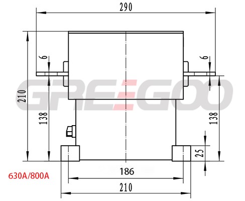
GVC30-630A/1.14KV |
GVC30-800A/1.14KV |
||||
|
Rated Operating Voltage(Ur) |
V |
1140 |
1140 |
1140 |
||||
|
Rated Operating Current (Ie) |
A |
400 |
630 |
800 |
||||
|
Rated Making Capacity (Im) |
kA |
4 |
7.56 |
8 |
||||
|
Rated Breaking Capacity (Ic) |
kA |
3.2 |
6.3 |
6.4 |
||||
|
Conventional Operating Performance Capacity |
kA |
2.4 |
3.78 |
4.8 |
||||
|
Rated Withstand Overload Current and Time |
kA/s |
3.2/10 |
5.04/10 |
8/4 |
||||
|
Rated |
Rated
|
Across Open Contacts |
kV |
10 |
||||
|
Between Phases |
kV |
4.2 |
||||||
|
To Earth |
kV |
4.2 |
||||||
|
Rated Impulse
|
Across Open Contacts |
kV |
12 |
|||||
|
Between Phases |
kV |
12 |
||||||
|
To Earth |
kV |
12 |
||||||
|
Main Circuit Contact Resistance |
μΩ |
≤200 |
≤150 |
≤120 |
||||
|
Rated Operating Frequency
|
AC3 |
operations |
600 |
|||||
|
AC4 |
120 |
|||||||
|
20s short time |
2000 |
|||||||
|
Electrical Endurance (Electrical Life) |
AC3 |
104 operations |
25 |
|||||
|
AC4 |
104 operations |
6 |
||||||
|
Mechanical Endurance (Mechanical Life) |
104 operations |
100 |
||||||
- Main Circuit Rated Voltage Ua: Can be AC/DC 110V, 220V, 380V or customized according to user requirements.
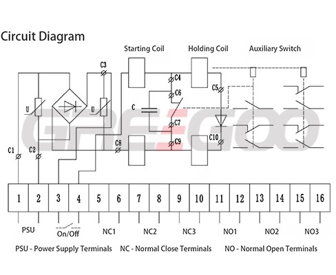
- Control Power: The starting power of the electric protection device is less than 2000W, and the holding power is less than 50W.
- Auxiliary Circuit Quantity: 3NC 3NO as standard, and if an electronic module control method is used, there can be 4NO 3NC.
- Auxiliary Contact Conventional Heating Current: 6A at AC380V; 10A at AC220V.
- Auxiliary Contact Rated Make and Break Current: 1A at AC380V, 2A at AC220V, 0.1A at DC220V.
- Power-Frequency Withstand Voltage: The main circuit can withstand a power-frequency withstand voltage of 2KV, excluding components.
- Operating Characteristics Closing and Opening Time: Closing time does not exceed 60ms; opening time does not exceed 60ms.
- Three-Phase Synchronism: The synchronization error does not exceed 2ms.
- Minimum Pull-in Voltage: Not less than 85% of the rated voltage; maximum release voltage is between 10% and 75% of the rated voltage.
Main Circuit
- The product features an integrated frame structure that ensures insulation while providing sufficient mechanical strength. The insulation withstands voltage levels up to 3kV.
- The vacuum switch tube uses products from well-known domestic manufacturers with mature technology, reliable quality, and a good market reputation.
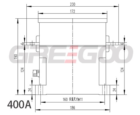
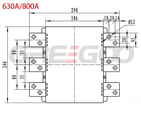
- The conductive busbar is designed to be aesthetically pleasing and durable, with two center distance options available to accommodate different user needs.
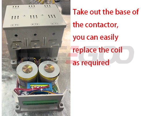
Electromagnetic System
- Utilizes a novel, fully sealed auxiliary switch, significantly improving the reliability and safety of the auxiliary switch.
- The optimized action structure reduces the coil's starting and holding power, thus lowering temperature rise, extending lifespan, and enhancing reliability.
- The actuator head of the auxiliary switch also employs buffering to reduce the impact force, thereby increasing the reliability of the auxiliary switch.
Action Structure
- The pivot support is designed to be flexible, with no sticking and minimal axial play, improving performance and consistency.
- A reasonable action mechanism ensures the coaxial movement of the vacuum tube's moving conductive rod, enhancing the performance and reliability of the contactor. The three-phase synchronicity and bounce characteristics are superior to similar products on the market.
- Enhanced contact pressure in the main contacts improves electrical performance and operational characteristics, surpassing similar products.
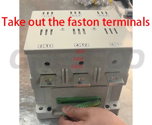
Ease of Use and Maintenance
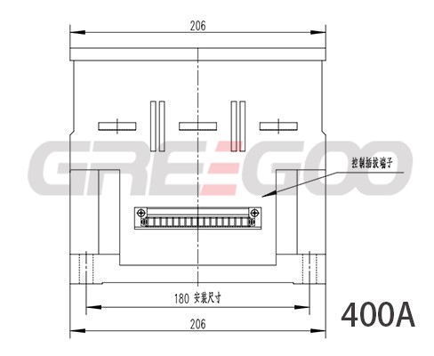
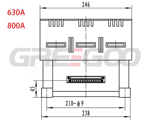
- The control circuit and auxiliary contacts are connected to wiring terminals, and each terminal is clearly marked with its function to avoid incorrect wiring, making it user-friendly and easy to maintain.
- Ambient Temperature: The highest surrounding air temperature should not exceed 40°C, and the 24-hour average should not exceed 35°C, with a minimum not lower than -15°C.
- Altitude: The installation site's altitude should not exceed 2000 meters.
- Relative Humidity: The relative humidity of the atmosphere should not exceed 50% when the surrounding air temperature is 40°C.
- Working Environment: There should be no exposure to rain, snow, open flames, explosive hazards, chemical corrosion, or intense vibrations.
- Installation Conditions: The installation surface should not be tilted more than 5 degrees from the horizontal or vertical plane.
- Pollution Level: Level III.
Need more information?
Contact us to request pricing, availability and customization options.

1.5KV Vacuum Contactor 160A 250A 400A
GVC11-160A/1.5KV, GVC11-250A/1.5KV, GVC11-400A/1.5KV vacuum contactor and starter
View More
Vacuum Contactor 250A and 400A
GVC6-250A/1.14KV GVC6-400A/1.14KV, GVC20-250A/1.5KV GVC20-400A/1.5KV
View More
630A 800A 1000A Vacuum Contactors
GVC20-630A/1.5KV, GVC20-800A/1.5KV, GVC20-1000A/1.5KV
View More
Vacuum Contactor 1250A 1600A 2000A 2KV
GVC40-1250A/2KV, GVC40-1600A/2KV, GVC40-2000A/2KV
View More