


Heatsink is not required three phase solid state relays
Home Products Solid State Relays (AC Switching)Special purpose SSR relaysHeatsink is not required three phase solid state relays


Product Details
Heatsink is not required three phase solid state relays
- There is optical isolation between the input and output circuits.
- Tri-color LEDs indicate the switching status.
- The solid-state contactless switch performs zero-crossing turn-on and turn-off, automatically extinguishing the arc.
- When contacts are in a continuous on state, power consumption is low, and there is minimal heat generation; thus, there is no need for cooling measures such as heatsinks or fans during use.
- The product has an ultra-small size, is convenient to install, and can directly replace ordinary relays or contactors.
- The product is mainly used for high-power electrical heating equipment, lighting equipment, reactive power compensation equipment, and electrical switching equipment that require a low switching frequency, prolonged continuous operation time, high working environment temperature, and poor ventilation facilities.
Specification
| Specification | GT34A | GT34B |
|---|---|---|
| Load Voltage | 440VAC | 660VAC |
| Maximum Load Current | 60~120 A | 120~180 A |
| On-State Resistance | ≤0.15Ω | ≤0.08Ω |
| Control Voltage | 12-15 VDC | |
| Control Current (Static) | ≤40mA | |
| Control Current (Transient) | ≤0.3A | |
| On/Off Pulse Width | ≥0.5S | |
| Turn-On/Turn-Off Time | ≤10 mS / ≤0.5 S | |
| Off-State Voltage | 800V | 1500V |
| Isolation Voltage | ≥1800 V | |
| Insulation Voltage | ≥2000 V | |
| Insulation Resistance | ≥100 MΩ | |
| Power Frequency | 50~60 HZ | |
| Operating Temperature | -20~75 ℃ | |
| Load Current Safety Factor (Resistive) | 2.5-3 times of rated current | |
| Load Current Safety Factor (Capacitive/Inductive) | 3-5 times of rated current | |
Notes while using
- When selecting a product, it is important to consider the nature of the load and to leave different margins for current and voltage ratings. For a resistive load, the selection can be made at 2.5 to 3 times the load current. For inductive or capacitive loads, the selection should be at 3 to 5 times the load current. Additionally, overcurrent protection measures, such as fast-acting fuses or circuit breakers, should be included in the load circuit to prevent short circuits.
- For inductive (capacitive) loads, overvoltage protection should be applied at the output to prevent thyristor overvoltage breakdown. This can be done by paralleling a Metal Oxide Varistor (MOV) at the output. The MOV should be selected as follows: for a 440V rating, choose between 470V to 680V; for a 660V rating, choose between 1100V to 1200V. Alternatively, an AC overvoltage protection absorber produced by the factory can be used.
- Since this model of solid-state relay uses a composite material structure at the output end, it operates at a lower frequency. If it is to work at high switching frequencies for extended periods, additional heat sinks for cooling may be necessary.
- Because the main switching element of a solid-state relay has a memory function, when the control power supply is connected, the internal control circuit will automatically enter a clearing program, causing the main switch to cycle through an on-off state. This is a normal phenomenon. To prevent instantaneous current impact when starting use, the control power supply should be connected first, followed by the main power supply.
Inquiry
Need more information?
Contact us to request pricing, availability and customization options.
Related Products

Solid State Automatic Transfer Switch
20A to 100A 110-240VAC
View More
Heatsink is not required single phase solid state relay
60A to 180A, 240V, 440V, 660VAC, control voltage 12VDC/220VAC/12-15VDC
View More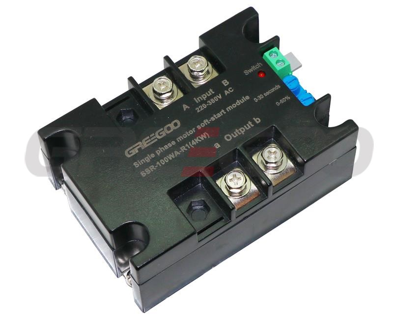
1 phase solid state soft starter
Soft start modules for single phase and three phase motor.
View More