


Charging and discharging DC Solid State Relays
Home Products DC to DC Solid State RelayAutomotive Solid State RelayCharging and discharging DC Solid State Relays
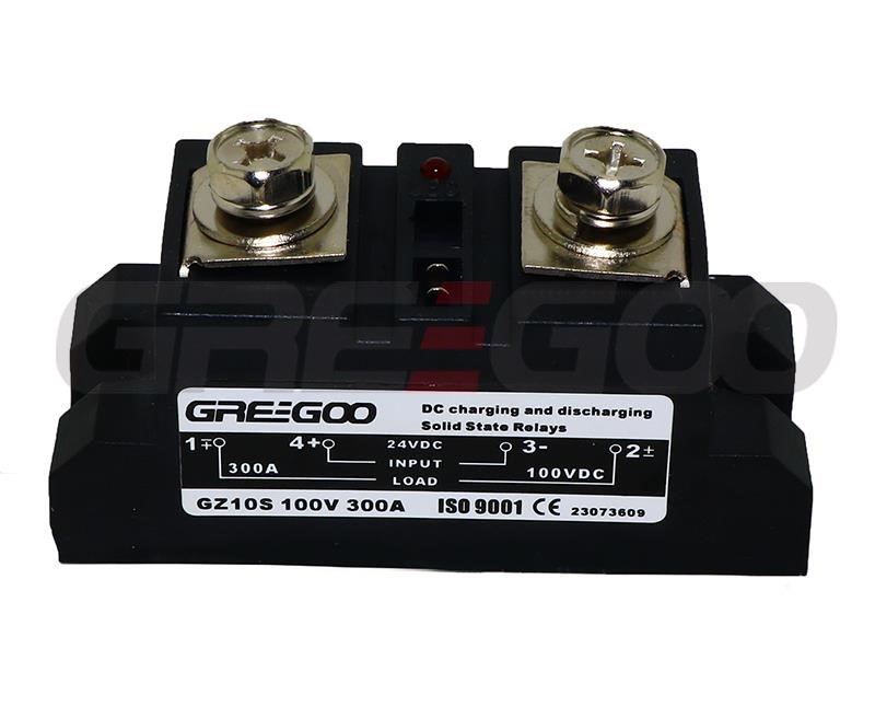
Charging and discharging DC Solid State Relays
- Optical and magnetic isolation between input and output circuits.
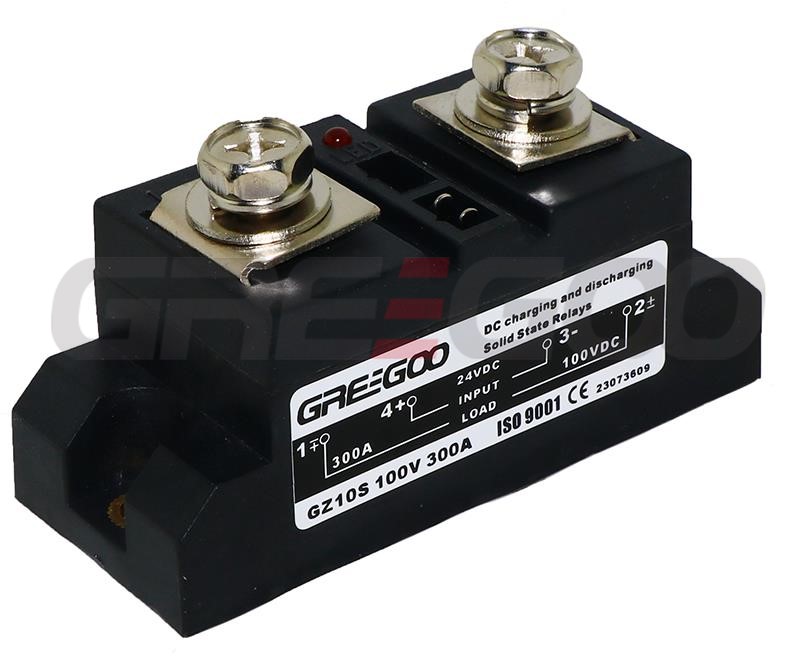
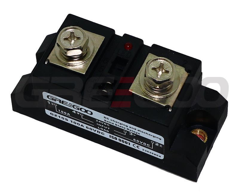
- LED indicator to show the operational status.
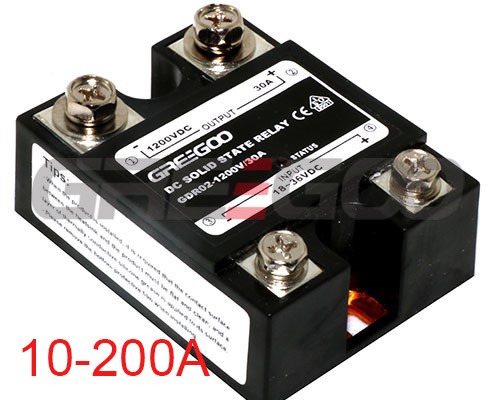
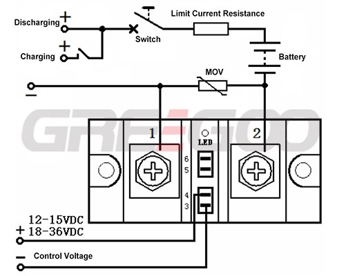
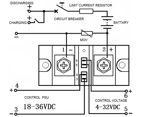
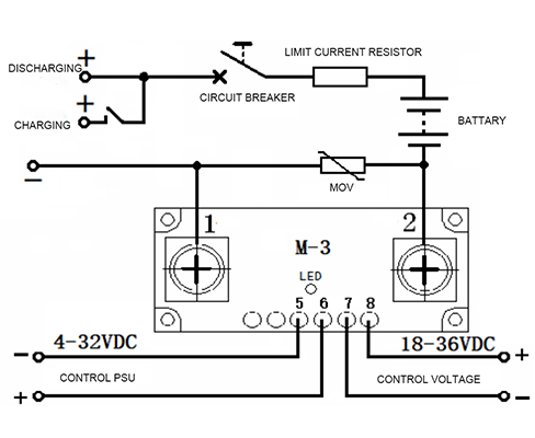
- The output terminal consists of a group of normally open solid-state switches capable of bidirectional DC switching without contact.
- Individual solid-state switches can be used for charging and discharging batteries and capacitors.
- The GZ10SL/GZ10CSL model has automatic protection functions for overcurrent and short circuits.
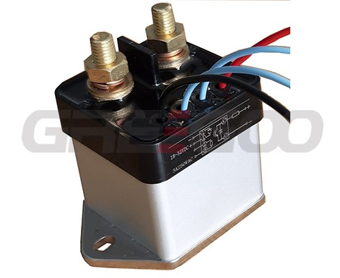
- It is packaged in a solid enclosure, resistant to corrosion and shock, ensuring stable and reliable operation.
- This product is used for DC charging and discharging switches in electric vehicles or battery power supplies.
|
Model |
GZ10S / GZ10SL |
||
|
Input |
Control Voltage |
12~15VDC; 18~36VDC |
|
|
Control Current |
≤80 mA |
||
|
Start Current |
≥ 60 mA |
||
|
Turn off Voltage |
12~15VDC≤10VDC; 18~36VDC≤12VDC |
||
|
Output |
Switching On/off time |
≤ 0.35 mS |
|
|
Max. Voltage |
60V, 100V, 200V, 600V, 1200V |
||
|
Max. Current |
30~400A |
||
|
On state voltage drop |
60V≤0.5V, 100V≤0.8V, 200V≤1.5V, 600V≤4.2V, 1200V≤5.0V |
||
|
Off state voltage |
60V, 100V, 200V, 600V, 1200V |
||
|
Protection |
Blank - without protection, L - with over-current and short-circuit protection, @ 50% of rating current. |
||
|
Performance Parameters |
Isolation Voltage |
≥ 2000 V |
|
|
Insulation Voltage |
≥ 2500 V |
||
|
Temperature Range |
-30 ~ 75 ℃ |
||
|
Power frequency |
10-1000 HZ |
||
|
Heatsink |
Install a heat sink with a fan |
||
|
Load tips |
For resistive loads, use 2-3 times the rated value. For inductive loads, use 3-4 times the rated value. |
||
|
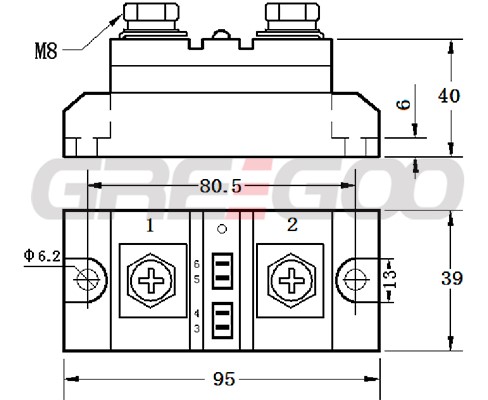
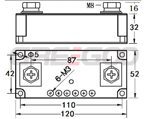
Dimensions |
95×39×40mm or 120×52×32mm |
||
 |
 |
|
Model |
GZ10CS / GZ10CSL |
||
|
Input |
Control power supply |
12~15VDC/2W; 18~36VDC/2W |
|
| Control Voltage | 4-32VDC | ||
|
Control Current |
8-20 mA |
||
|
|
|||
|
Turn off Voltage |
12~15VDC≤10VDC; 18~36VDC≤12VDC |
||
|
Output |
Switching On/off time |
≤ 0.15 mS |
|
|
Max. Voltage |
60V, 100V, 200V, 600V, 1200V |
||
|
Max. Current |
30~200A |
||
|
On state voltage drop |
60V≤0.5V, 100V≤0.8V, 200V≤1.5V, 600V≤4.2V, 1200V≤5.0V |
||
|
Off state voltage |
60V, 100V, 200V, 600V, 1200V |
||
|
Protection |
Blank - without protection, L - with over-current and short-circuit protection, @ 50% of rating current. |
||
|
Performance Parameters |
Isolation Voltage |
≥ 2000 V |
|
|
Insulation Voltage |
≥ 2500 V |
||
|
Temperature Range |
-30 ~ 75 ℃ |
||
|
Power frequency |
10-1000 HZ |
||
|
Heatsink |
Install a heat sink with a fan |
||
|
Load tips |
For resistive loads, use 2-3 times the rated value. For inductive loads, use 3-4 times the rated value. |
||
|
Dimensions |
95×39×40mm or 120×52×32mm |
||
 |
 |
- Allow for different margins in current rating based on the nature of the load. (For resistive loads, choose 2-3 times the load current. For inductive or capacitive loads, choose 3-4 times the load current.)
- The actual load current is greatly influenced by the ambient temperature. When the ambient temperature is high or the heat dissipation conditions are poor, increase the current capacity. To prevent short circuits in the load circuit during use, overload protection should be added. For specifications above 600V, GZ10SL/GZ10CSL current-protected solid-state relays can be used as an option.
- To prevent the generation of inductive counter electromotive force due to long output power lines, overvoltage protectors should be connected in parallel at the output end to protect the solid-state switch from damage during overvoltage. The selection of metal oxide varistors (MOV): choose a value of 80% of the rated voltage of the solid-state relay.
- The contact surface between the matching heat sink and this product must be flat and smooth. Apply a layer of thermal conductive silicone grease on the surface. When fixing it, tighten the screws symmetrically with spring washers and flat washers to prevent loosening due to thermal expansion and contraction of the screws.
- Ensure that the screws are properly tightened to prevent loosening due to thermal expansion and contraction.
Need more information?
Contact us to request pricing, availability and customization options.