


BY7-80 SPD
Home Products Surge Protection DeviceT2 SPDBY7-80 SPD
BY7-80 SPD
| Item | Specification |
|---|---|
| Model | BY7-80-385 |
| Nominal AC Voltage of the System Uo(V) | ~230/400 |
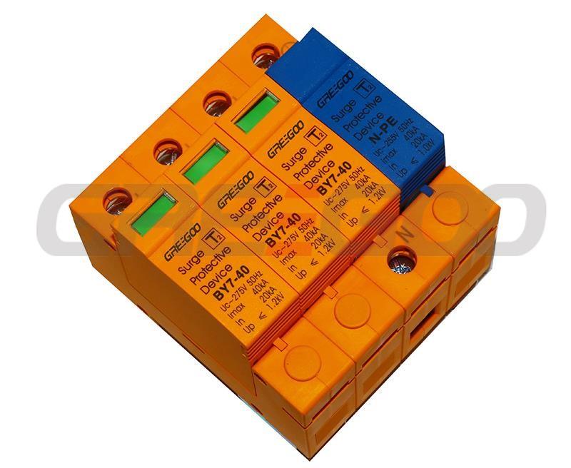
| Max. Continuous Operating Voltage Uc(V) | ~385/255 (N-PE) |
| Nominal Discharge Current In(kA) | 40 |
| Max. Discharge Current Imax(kA) | 80 |
| Voltage Protection Level Up(kV) | 2.0 |
| Response Time TA | MOV: 25 ns / GDT: 100 ns |
| Max. Backup Fuse | 200A gL/gG |
| Wiring | 4mm2~35mm2 |
| Protection Grade of the Shell | IP20 |
| Material | PA66 |
| Flameproof Grade | Comply with UL94-V0 |
| Short Circuit Current Rating Isccr | 1000A |
| Status Indicator | Green: Functional / Red: Failed |
| Output Contact | C-NC: Conduction / C-NO: Open |
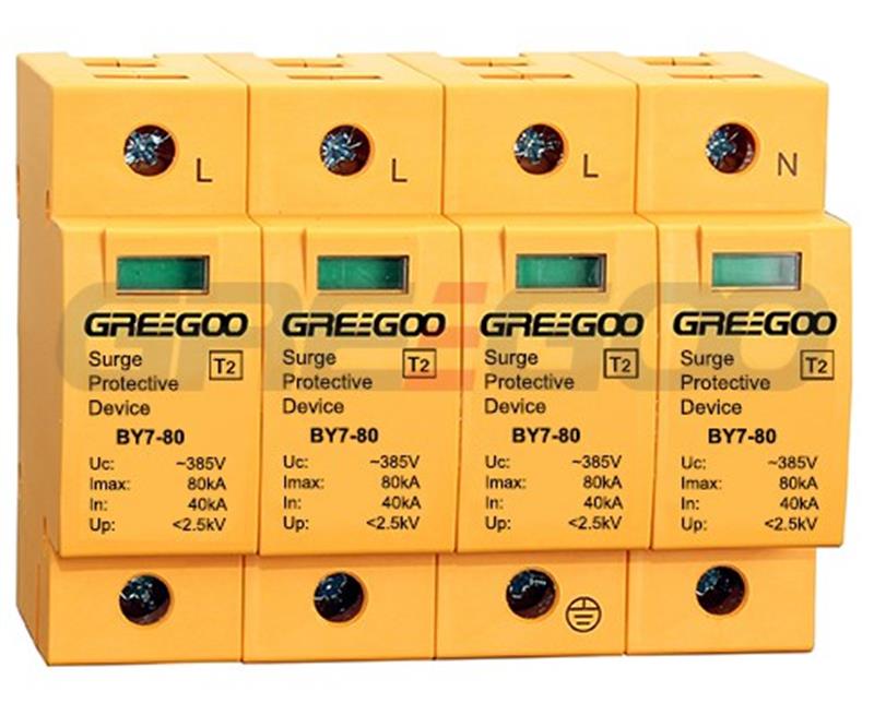
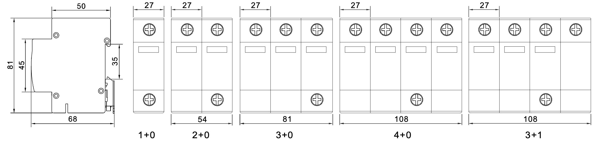
| Combination Method | 1 0, 2 0, 3 0, 4 0, 3 1 |
| Applicable Power Supply System | TN, TT |
| Installation Method | 35mm DIN rail |
| Ambient Temperature | -5°C~ 40°C |
| Ambient Humidity | 5%~95% |
| Altitude | <2000m |
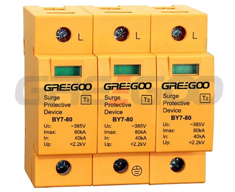
The BY7-80 series Surge Protection Device (SPD) features a dependable voltage protection level and a robust overload characteristic, coupled with a strong discharge current capacity, making it ideal for lightning protection in AC low voltage distribution systems. Incorporating a high-energy Metal Oxide Varistor (MOV) chip, the BY7-80 series SPD offers a rapid response time and reliable protection functions. This product is in full compliance with the IEC 61643-11:2011 standard.


| Desctription | Symbol | Unit | Parameters & Models | |||
| Rated operational voltage | Uc | V | 275 | 320 | 385 | 440 |
| Nominal discharge current | In | kA | 40 | 40 | 40 | 40 |
| Maximum discharge current | Imax | kA | 80 | 80 | 80 | 80 |
| Voltage protection level | Up | Kv | 2.0 | 2.2 | 2.5 | 3.0 |
| Protection degree | IP | 20 | 20 | 20 | 20 | |
| Response time | ns | 25 | 25 | 25 | 25 | |
| Fuse | A | 100 | 100 | 100 | 100 | |
| Material | PA6 | PA6 | PA6 | PA6 | ||
| Fire retardent (comply with) | UL94V-0 | UL94V-1 | UL94V-2 | UL94V-3 | ||
| Standards | IEC61643-1:1998 | |||||
| Single Phase Model |
L/N L,N |
BY7-80/1-275 BY7-80/2-275 |
BY7-80/1-320 BY7-80/2-320 |
BY7-80/1-385 BY7-80/2-385 |
BY7-80/1-440 BY7-80/2-440 |
|
| L/N NPE | BY7-80/1 1-275 | BY7-80/1 1-320 | BY7-80/1 1-385 | BY7-80/1 1-440 | ||
| Three phase Model | L1,L2,L3 | BY7-80/3-275 | BY7-80/3-320 | BY7-80/3-385 | BY7-80/3-440 | |
| L1,L2,L3,N | BY7-80/4-275 | BY7-80/4-320 | BY7-80/4-385 | BY7-80/4-440 | ||
| L1,L2,L3,N NPE | BY7-80/3 1-275 | BY7-80/3 1-320 | BY7-80/3 1-385 | BY7-80/3 1-440 | ||
| Local indication: Green indicates normal state and red indicates failure. | ||||||
Need more information?
Contact us to request pricing, availability and customization options.
T2 BY7-40/3+1-385X surge protective device
40kA, 3+1, full protection, T2 zone.
View More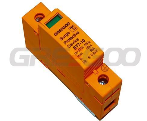
BY7-10 SPD
10kA SPD, CE, CB, RoHs approval from Dekra.
View More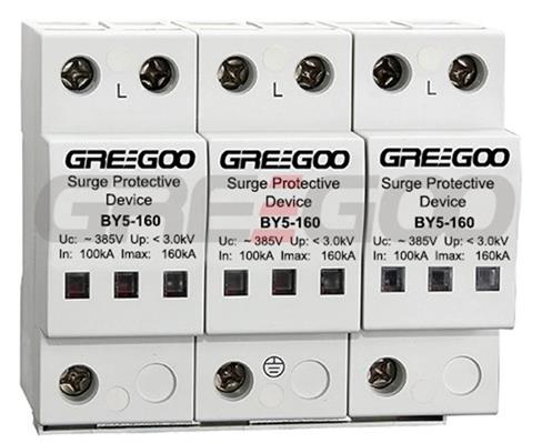
BY5-120 SPD
120kA 3 phase surge protective device, spd.
View More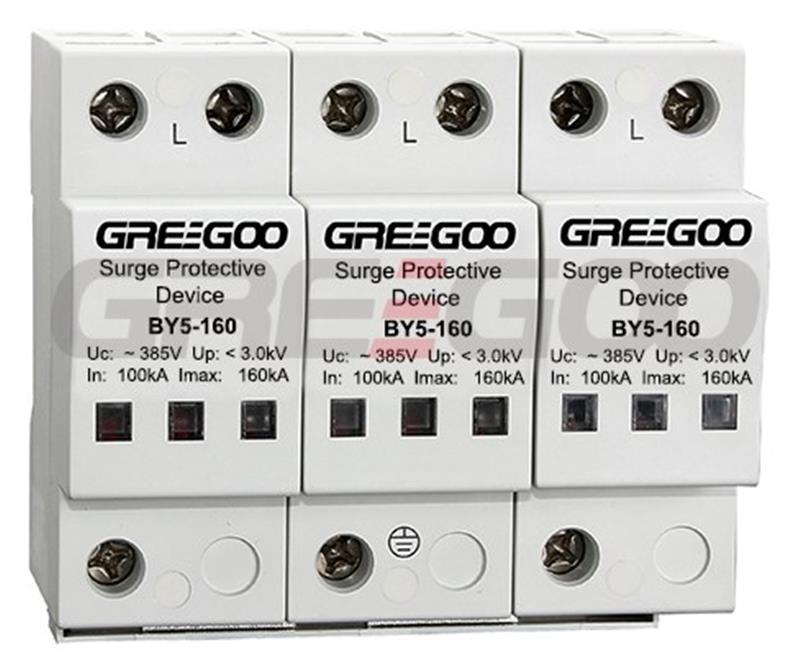
BY5-160 SPD Surge Arrester
160kA 3 phase surge protection device, L1,L2,L3 and L1,L2,L3,N.
View More