


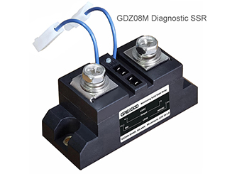
Built-in Over-temperature Protection Operating Principle of GDZ08M Monitoring AC Solid State Relay
The allowable operating temperature range of the whole device is -30 ℃ to 90 ℃. The protection function will activate once the temperature exceeds the safety threshold.
1. Normal Operating State
2. Over-temperature Trigger Stage (Insufficient Heat Dissipation / Heat Generation from Overload)
Insufficiently sized heat sinks, stalled cooling fans, loose mounting screws or long-term load overload will cause continuous temperature rise of the housing and chips until the preset protection threshold is reached:
a. The resistance value of the thermistor changes, and the voltage signal is transmitted to the comparison circuit to identify an over-temperature fault.
b. The internal circuit automatically cuts off the power circuit on the output side, de-energizing the load to stop heat generation.
c. Fault feedback is triggered simultaneously:
- Panel indicator status changes: the red light turns on, or the red and green lights flash alternately.
- Auxiliary alarm contacts A and B switch from normally open to closed, which can be connected to external alarms and protective circuit breakers.
d. Visible symptom: the load turns on and off intermittently (cyclic startup and shutdown), which is specified in the document as a typical feature of over-temperature protection.
3. Automatic Recovery (Thermal Hysteresis Reset)
- The internal protection circuit lifts the lock, and the output resumes conduction.
- The indicator light returns to steady green, and contacts A and B revert to normally open status.
- The load restarts operation after being re-energized.
- Pure over-temperature fault: red light illuminates, contacts A and B close, and the load cycles on and off intermittently.
- Continuous alternating flashing of red and green lights during operation: indicates composite faults including over-temperature, open load and component damage. The document requires immediate shutdown for inspection and maintenance.
- Units with rated current ≥20A must be equipped with heat sinks; otherwise, over-temperature protection will activate easily.
- Units with rated current ≥120A require both a heat sink and a forced air cooling fan.
- Installation specifications: apply thermal grease on contact surfaces and fasten screws symmetrically. Poor contact will drastically increase temperature rise and trigger repeated over-temperature cut-offs.
- Prevent thermal breakdown of power semiconductors under high temperatures and permanent burnout of the solid state relay.
- Eliminate safety hazards such as wire aging and fire risks caused by sustained high temperatures.
- Provide dual early warnings via indicator lights and passive alarm contacts to alert operators of heat dissipation faults in advance, facilitating troubleshooting of heat sinks, cooling fans and improper installation workmanship.
- Loose mounting screws leading to poor thermal contact.
- Damaged or stalled cooling fans.
- Undersized heat sinks with insufficient heat dissipation margin.
- Long-term load overload due to improper model selection without reserving 2–3 times current margin for resistive loads or 3–4 times for inductive loads.
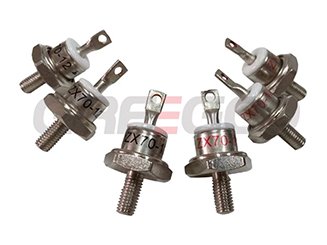
Rotating Diode vs. Standard Recovery Diode: Key Difference and Application
A rotating diode is a special type of rectifier diode used in the brushless excitation system of synchronous generators (alternators).
Read More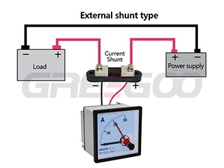
How to use DC Current Shunt? A Comprehensive Guide on DC Shunt Resistor
Understanding DC Current Shunts, A Comprehensive Guide.
Read More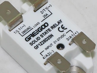
Mini Puck Solid-State Relay: A Compact and Reliable High-Efficiency Switching Solution
Despite its small size, it remains highly reliable. The GF1 uses back-to-back thyristors for switching, which are more durable than traditional triacs.
Read More
Technical Comparison: GRH-12 High-Speed VCB vs. Standard VS1 Vacuum Circuit Breaker
Upgrade your VS1 without cabinet modifications or downtime: Replace standard 50ms+ response times with 5ms ultra-fast opening.
Read More