


Common Failure Modes of Thyristor Modules and Preventive Measures
Thyristor (SCR) modules are critical components in power electronic systems, and their reliability directly impacts overall system stability. Based on field experience and manufacturer technical data, common failure modes can be categorized into three main types: electrical overstress, thermal overstress, and drive-related issues.
1. Overcurrent Burnout
This is the most direct and common failure mode, manifested as module explosion, internal wire fusion, or chip burnout.
Main Causes:
-
Load Short Circuit: Short circuits in motors, cables, or the load side generate surge currents far exceeding the module's rating.
-
False Triggering: Control circuit interference causes triggering at incorrect times (e.g., before voltage zero-crossing), leading to high instantaneous current.
-
Excessive di/dt: Excessive rate of current change during turn-on causes current concentration in local areas of the chip, creating hot spots and burnout.
-
Incorrect Selection: Module rated current is insufficient to handle the load's inrush or RMS current.
2. Overvoltage Breakdown
Manifests as internal short circuit within the module, with a sharp drop in anode-cathode impedance.
Main Causes:
-
Switching Surges: Instantaneous high voltage generated by switching inductive loads (e.g., contactors, relays) on the grid.
-
Lightning Surges: Extremely high voltage introduced into the grid via lightning strikes.
-
Commutation Overvoltage: When the module turns off, parasitic inductance in the circuit (e.g., busbar stray inductance) can induce high voltage (V = L * di/dt).
-
Excessive Voltage Rise Rate (dv/dt): Even without a trigger signal, an excessive anode voltage rise rate can cause false triggering, potentially leading to overcurrent.
3. Overheating Failure
This is a chronic but fatal failure mode and a primary cause of end-of-life for most modules.
Main Causes:
-
Poor Heat Dissipation: Undersized heat sink, fan failure, blocked air ducts, dried-up or unevenly applied thermal grease, causing junction temperature (Tj) to exceed the maximum rating (typically 125°C or 150°C).
-
Conduction Losses: Prolonged operation at high conduction angles or near rated current generates significant heat.
-
Switching Losses: In high-frequency applications (e.g., high-frequency inverters), losses during switching transitions become the main heat source.
-
High Ambient Temperature: Poor ventilation in the equipment installation location causes ambient temperature to exceed the module's specified limit.
4. Gate Drive Failure
Manifests as the module failing to turn on properly or unstable triggering.
Main Causes:
-
Insufficient Drive Signal: Trigger current (IGT) or trigger voltage (VGT) is too low, preventing reliable turn-on of the thyristor.
-
Excessive Drive Signal: Excessive gate current or voltage can damage the PN junction between the gate and cathode.
-
Drive Signal Interference: Control lines running parallel to main power lines introduce noise, causing false triggering or failure to trigger.
-
Open or Short Circuit in Gate: Loose connectors or cable wear lead to abnormalities in the gate circuit.
5. Mechanical Stress Damage
Main Causes:
-
Improper Installation: Excessive or uneven mounting screw torque causes mechanical stress cracks in the ceramic substrate (DBC) or chip.
-
Thermal Cycling Fatigue: Frequent equipment start-stop cycles subject the module chip, solder, and substrate to repeated stress cycles due to differing coefficients of thermal expansion, eventually leading to bond wire lift-off or solder layer fatigue cracking.
II. Preventive Measures at the Circuit Design Level
Excellent circuit design is the first and most effective line of defense against failures.
1. Overcurrent Protection
Fast-Acting Fuses: Connect fast-acting fuses in series with the AC input terminals of the module. Their rated current should be slightly lower than the module's rated RMS current, serving as the final safety barrier.
Current Sensing and Software Protection: Use Hall effect current sensors to monitor load current in real-time. Set overcurrent thresholds in the control program to block trigger signals immediately upon detection of overcurrent ("soft protection").
di/dt Limiting: Connect an air-core reactor (several µH to tens of µH) in series in the main circuit to effectively limit the rate of current change at turn-on.
2. Overvoltage Protection
RC Snubber Circuit: This is the core protective measure. Connect an RC circuit in parallel between the anode and cathode of each thyristor module.
-
Resistor (R): Dissipates energy.
-
Capacitor (C): Absorbs voltage surges, reducing peak voltage and dv/dt.
-
Selection Basis: Calculated based on module current and line inductance.
Varistor (MOV): Connect a metal oxide varistor in parallel at the module's input terminals (AC side) to absorb high-energy surges like lightning strikes and switching surges. Its clamping voltage should be higher than the normal operating peak voltage but lower than the module's repetitive peak voltage.
Freewheeling Diode: Connect a freewheeling diode in reverse parallel across inductive loads to provide a discharge path for the back EMF generated during turn-off, protecting the module from overvoltage impacts.
3. Thermal Management and Heat Sink Design
Heat Sink Calculation: Calculate the thermal resistance of the heat sink based on the module's maximum power dissipation, maximum ambient temperature, and required junction temperature. Select a sufficiently large heat sink.
Forced Air/Water Cooling: For medium to high-power applications, forced cooling is essential. Use cooling fans with alarm functions and monitor airflow or water flow.
Temperature Monitoring: Use intelligent modules with built-in NTC thermistors or install temperature sensors on the heat sink. Integrate the temperature signal into the control system for overtemperature alarms and shutdown.
4. Gate Drive Circuit Design
Trigger Pulse Requirements: Provide trigger pulses with sufficient amplitude and sharp rise time. The pulse current is typically 3-5 times the required IGT of the module, and the pulse width must ensure conduction until the anode current exceeds the latching current.
Trigger Isolation: Use pulse transformers or optocouplers (e.g., TLP series) to provide electrical isolation for the drive circuit, preventing high voltage from the main circuit from entering the control circuit.
Noise Immunity Wiring:
-
Use twisted-pair shielded cables for gate drive lines and keep them away from main power lines.
-
Ground the shield at one end only.
-
Connect a small capacitor (e.g., 100nF) and a small resistor (e.g., 10Ω) in parallel close to the gate and cathode pins to absorb high-frequency noise.
III. Operational and Maintenance Level Preventive Measures
Even the best design requires correct use and maintenance.
1. Correct Installation
Strictly follow the torque and sequence (cross-tightening) specified in the datasheet when mounting the module to the heat sink. Apply high-quality thermal grease evenly to ensure minimal thermal contact resistance.
2. Regular Inspection and Maintenance
Dust Removal: Regularly clean dust from heat sink fins and fans to maintain cooling efficiency.
Check Fasteners: Periodically check mounting screws and electrical connection points for looseness to prevent increased contact resistance and heating.
Monitor Operating Status: Use a thermal imager to regularly scan modules and busbar connections, addressing abnormal hot spots promptly.
3. Establish Early Warning Mechanisms
Leverage the monitoring functions of the control system to log historical data such as operating current and heat sink temperature. When trends become abnormal (e.g., slowly rising temperature), early warnings can be issued to schedule maintenance and avoid unplanned downtime.
Failures in thyristor modules result from the combined effects of electrical, thermal, and mechanical stress. Preventive measures must be systematic:
-
Design Phase: Build multiple layers of protection using RC snubbers, fast fuses, current sensors, and optimized drive and heat dissipation.
-
Application Phase: Correct installation and standardized wiring are the foundation.
-
Maintenance Phase: Regular dust cleaning, fastener checks, and condition monitoring are key to extending service life.
By adopting this integrated "Design-Application-Maintenance" approach, the failure rate of thyristor modules can be minimized, ensuring the stable and long-term operation of industrial equipment.
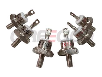
Rotating Diode vs. Standard Recovery Diode: Key Difference and Application
A rotating diode is a special type of rectifier diode used in the brushless excitation system of synchronous generators (alternators).
Read More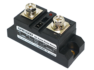
Advantages of Low Voltage Drop DC Solid-State Relays - Heatsink is not required
Low voltage drop DC solid-state relays offer significant advantages in terms of efficiency, low heat generation, and high reliability, making them particularly suitable for applications requiring high efficiency and low energy consumption.
Read More
Fast Recovery Epitaxial Diode vs Fast Recovery Diode Module
Fast Recovery Epitaxial Diode vs Fast Recovery Diode Module, what's their difference from
Read More
Ultra-fast switching - 5ms opening or closing time - vacuum contactors and vacuum circuit breakers
Greegoo can support customized parameters for specific needs of high speed vacuum contactors and vacuum circuit breakers.
Read More