


The IGBT topology comparison and selection guide
In practical IGBT module selection, the circuit topology determines how the chips are integrated, the pin configuration, and the target application scenarios.
Below is a comparison of common IGBT module topologies, their circuit features, and typical applications:
1. Common IGBT Topologies & Differences
1. Single Switch
-
Features: Contains only 1 IGBT chip inside the module (usually paired with an anti-parallel freewheeling diode, FWD).
-
Applications: Ultra-high-power inverters/switches, chopper circuits, DC/DC converters, and high-power induction heating.
-
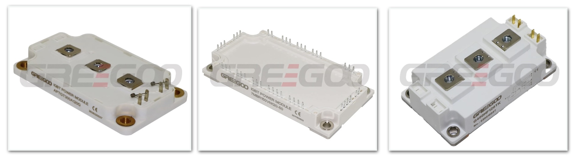
Representative Models: Such as Single Switch IGBT Module (300A–1200A / 1200V–1700V).
2. Half Bridge (Phase Leg / Dual Switch)
-
Features: Integrates 2 IGBT chips connected in series (upper arm and lower arm). Output pins connect to the upper collector , middle phase node , and lower emitter .
-
Applications: Three-phase inverters (built using 3 half-bridge modules), single-phase H-bridge inverters, high-frequency SMPS, and high-power variable frequency drives (VFDs).
-
Representative Models: Industry-standard 62mm or PrimePACK packaged half-bridge modules (e.g., Half Bridge IGBT Module FF600R12ME4, SKM200GB125DN).
3. Chopper Module
-
Features: Composed of 1 IGBT and 1–2 freewheeling/freewheeling-reverse diodes. Common variants include Buck, Boost, or Brake Chopper topologies.
-
Applications: DC traction locomotives (subways, light rail), DC motor speed control, and VFD brake units.
-
Representative Models: Such as Chopper IGBT Module.
4. Sixpack (3-Phase Bridge / Full Bridge)
-
Features: Integrates 6 IGBT chips within a single module, forming a complete 3-phase inverter bridge (U, V, W upper/lower arms).
-
Applications: Small-to-medium power 3-phase AC motor drives, servo drives, UPS systems, and compact VFDs.
-
Advantages: Significantly reduces PCB footprint and parasitic inductance, making it easy to build 3-phase inverter circuits.
-
Representative Models: Such as Sixpack IGBT Module (e.g., SEMiX101GD126HDs, BSM150GT120DN2).
5. PIM / CIB Module (Power Integrated Module / Converter-Inverter-Brake)
-
Features: A highly integrated "3-in-1" topology containing:
-
Rectifier Bridge (3-phase input diode bridge)
-
Brake Chopper (1 IGBT 1 Diode)
-
Inverter Bridge (6pack 3-phase inverter)
-
Most units also include a built-in NTC thermistor for temperature monitoring.
-
-
Applications: General-purpose VFDs, industrial servo drives, and control cabinets.
-
Advantages: Simplest wiring, extremely high power density, enabling complete AC-DC-AC conversion in a single footprint.
-
Representative Models: Such as PIM IGBT Modules (e.g., 7MBR50VP120-50, FP50R12KT4G).
6. 3-Level Topology (NPC / TNPC)
-
Features: Unlike traditional 2-level topologies (which only output and ), 3-level topologies include additional switches and clamping diodes to output three voltage states: , (neutral point), and .
-
Applications: High-voltage/high-power PV inverters, wind turbine converters, large-scale energy storage PCS, and medium-voltage drives.
-
Advantages: Lower harmonic content in output voltage, smaller filter inductor requirement, lower switching losses, and higher efficiency in high-voltage, high-power setups.
-
Representative Models: Such as 3 Level IGBT Module.

2. Topology Comparison & Selection Guide
For designing standard VFD/servo systems, PIM (CIB) modules are typically preferred for small-to-medium power, while Half Bridge / Sixpack combinations suit higher power ranges. For PV/renewable grid-tied applications, 3-level topologies are widely used.
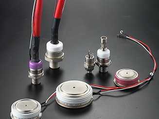
Stud Semiconductors vs. Capsule Semiconductors
Stud and capsule semiconductors are high-power, industrial-grade components designed for heavy-duty applications, featuring robust packaging for superior thermal management and electrical performance.
Read More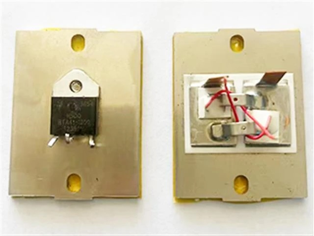
Differences Between TRIAC Output SSR (GD series SSR) and SCR Output SSR (GDH series SSR)
GD and GDH series single phase solid state relay, what's their difference?
Read More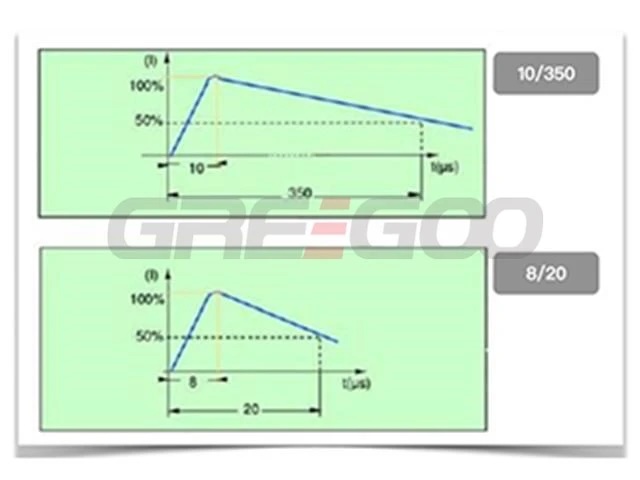
What is the main difference between 8/20μs and 10/350μs in SPD?
The terms "8/20μs" and "10/350μs" refer to different surge waveforms used to characterize the performance and capability of Surge Protective Devices (SPDs).
Read More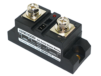
Advantages of Low Voltage Drop DC Solid-State Relays - Heatsink is not required
Low voltage drop DC solid-state relays offer significant advantages in terms of efficiency, low heat generation, and high reliability, making them particularly suitable for applications requiring high efficiency and low energy consumption.
Read More

We value your privacy
We use cookies to enhance your browsing experience, serve personalized ads or content, and analyze our traffic. By clicking "Accept All", you consent to our use of cookies.
